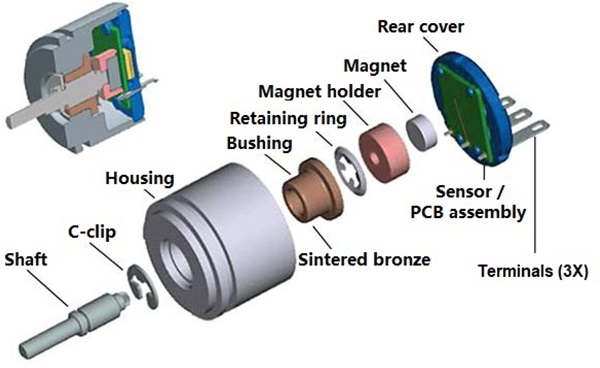
If you have the opportunity to disassemble a magnetic rotary encoder, you will usually see an internal structure like the one shown above. The magnetic encoder is composed of a mechanical shaft, a shell structure, a PCB assembly at the end of the encoder, and a small disc magnet rotating with the shaft at the end of the mechanical shaft.
How does the magnetic encoder measure the rotation position feedback?
Hall Effect: the production of potential difference across a conductor carrying on electric current when a magnetic field is applied in the direction perpendicular to that of current flowing.
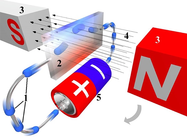
If the magnetic field applied to the conductor is rotated in the direction shown by the arrow above with the current flow path as the axis, the Hall potential difference will change due to the change of the angle between the magnetic field and the conductor, and the change trend of the potential difference is a sinusoidal curve. Therefore, based on the voltage on both sides of the energized conductor, the rotation angle of the magnetic field can be calculated reversely. This is the basic working mechanism of a magnetic encoder when measuring rotation position feedback.
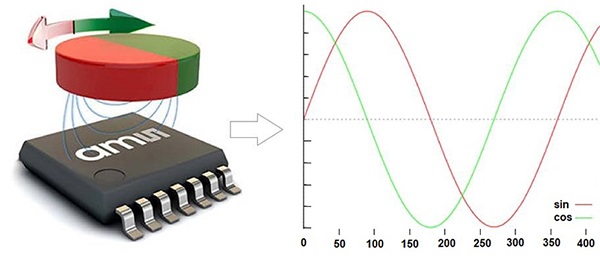
Similar to the principle that the resolver uses two sets of mutually perpendicular output coils, two (or two pairs) hall induction elements with mutually perpendicular current directions are also required in the magnetic encoder to ensure the unique correspondence between the rotating position of the magnetic field and the output voltage (combination).
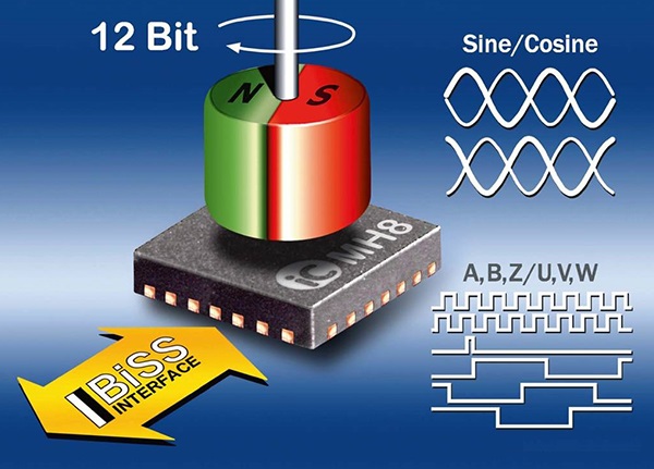
Nowadays, Hall sensors (chips) used in magnetic encoders generally have a high degree of integration, which not only integrates hall semiconductor components and related signal processing and regulation circuits, but also integrates various types of signal output modules, such as sine and cosine analog signals, square wave digital level signals or bus communication output units.
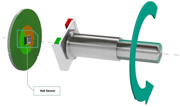
In this way, install a permanent magnet like sintered Neodymium magnet that generates a magnetic field at the end of the encoder rotating shaft, place the hall sensor chip mentioned above on a PCB circuit board, and approach the permanent magnet at the end of the encoder shaft according to certain requirements (direction and distance).
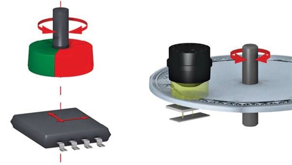
By analyzing the voltage signal output from the hall sensor through the PCB circuit board, the rotating position of the encoder rotor can be identified.
The structure and working principle of the magnetic encode decides the special requirement about this permanent magnet for example magnet material, magnet shape, magnetization direction, etc. Normally diametrically magnetized Neodymium magnet disc is the best magnet option. Ningbo Horizon Magnetics are experienced in supplying many manufacturers of magnetic encodes with some sizes of diametrical Neodymium disk magnets, D6x2.5mm and D10x2.5mm diametric disc Neodymium magnets of which are the most popular models.
It can be seen that compared with the traditional optical encoder, the magnetic encoder does not need a complex code disk and light source, the number of components is less, and the detection structure is simpler. Moreover, Hall element itself also has many advantages, such as firm structure, small size, light weight, long service life, vibration resistance, not afraid of dust, oil, water vapor and salt fog pollution or corrosion wait.
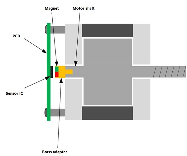
When the magnetic encoder technology is applied to the rotation position feedback of the electric motor, the sintered NdFeB magnet cylinder of the magnetic encoder can be directly installed at the end of the motor shaft. In this way, it can eliminate the transitional coupling bearing (or coupling) required when using the traditional feedback encoder, and achieve contactless position measurement, which reduces the risk of encoder failure (or even damage) due to the vibration of the mechanical shaft during the operation of the electric motor. Therefore it helps to improve the stability of electric motor operation.

Copyright © Ningbo Horizon Magnetic Technologies Co., Ltd. All Rights Reserved Sitemap